Below is a post from the past discussing some additional fast charging methods
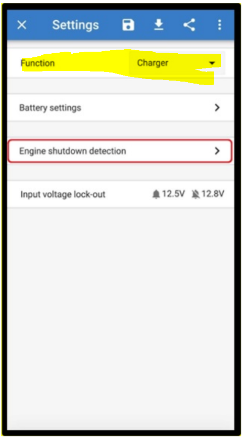
What is the best settings for Orion 12/25 10A and AC200P? Power Supply or Charger Mode, What Battery Mode (Lifepo4 or other)? The Detection for Running Engine is only available in Charger Mode :-/
Correct. This situation works only if you connect directly to the battery with short, thick wires and the vehicle having sufficient excess alternator capacity of around 100 amps so the alternator is not operating at full load
I don’t understand the question based on the information provided
In the Victron Connect App i have two option: Charger Mode oder Power Supply.
What is the best Mode for load the AC200P over the motor engine (alternator)?
12.8 would be what I would suggest for the engine shut down detect voltage.
Ok. This seems to be exactly what I was looking for. A friend of mine has a Bluetti that she uses in her converted skoolie for an evening power source. She generally travels 3-4 hours a day and charging over the cigarette lighter is not fast enough at 100w or so. If I were to attempt this as described by the thread starter I have some questions:
- Is the converter connected directly to the battery (always on)?
- Is the specified converter water-proof enough to mount in engine bay?
It seems relatively easy to mount the converter very close to battery with stand off tubes as well as attaching the fan for cooling. I am basically a hobbyist but this seems fairly straightforward (famous last words). My concern would be how to make this only draw when the engine is running. My friend is a bit absent minded and I have no doubt she will forget to manually switch off and drain the battery multiple times a week.
Thoughts? Am I over simplifying this?
Attach the converter to the battery but add a control line to the “ACC” signal so the converter can only power on with the engine running or in accessory mode.
Thanks. My “less-than-expert” status understands the concept but is unfamiliar with the phrase control line. Can you dive in a bit more on what that entails? Is it a thing or is it a way of wiring that is called a control line?
1- The converter would always be on unless you installed a switch. This could be done with a large capacity relay or battery solonoid switch
2- the unit appears water proof but I would install inside if feasible
Please do not overlook the important concepts in the last paragraph of Scott Benson’s original post: wire size (gauge) and over-current protection (fuse or circuit breaker) for the circuit feeding the converter.
The appropriate wire size depends on the amperage of the load, and the length of the wire run.
The maximum size of the fuse depends on the wire size; it is not related to the amperage of the load. That’s because the purpose of any fuse is to prevent a fire in the wiring. 12V systems can and do have failures that result in fires—not something you want in your expensive vehicle parked in your garage.
I would argue that the wiring from the converter to the Bluetti also needs over-current protection (appropriate for the size of the smallest wiring in that circuit). But I’m no expert.
Thanks S-B. The concept is understandable but again, due to my own ignorance, I can’t piece together the actual execution of this. Most solenoid diagrams I am seeing are for house battery setups and I cannot translate these with my pea-sized brain. Any chance you could explain or illustrate in a little more detail how you might wire in a solenoid for this type of setup?
Yeah. I left out that detail in my description but I do intend to follow all the recommendations. Those include the high amperage switch, 75 amp fuse/circuit-breaker, and the appropriate heavy gauge cables. I will be posting the parts and plan on here in advance for “approval”. ![]()
Something like a battery isolator solenoid switch or relay switch like these will carry the high current. The units functions as an electrically operated switch. One large lug connects to your battery, the other large lug would connect to your step up converter input power cable. The two small connectors on top…one would go to a 12 volt source and the other would go to the remote switch shown that would install inside the vehicle or a convenient place. This would be a manual operation. You could eliminate the manual switch and connect the small input connection to a 12 volt source that was on only when the key was in the run position. I personally prefer the manual switch method because you can then turn on or off the step up converter at will whereas if you wire it to a hot lead that is on any time the key is turned on you are also always running the step up converter any time the key is on.
I kind of like this one for the simplicity and price.:
https://www.amazon.com/Continuous-Switch-Starter-Charger-Contactor/dp/B08CXSGLKB/ref=sr_1_27?crid=2OJFE26Y65CGW&keywords=high+continueaous+current+solenoid+switch&qid=1645028853&sprefix=high+continueaous+current+solenoid+switch%2Caps%2C120&sr=8-27
1 Like
Excellent. Let me try and process this into a visual layout that makes sense to me. Thanks again

Hello Scott-Benson,
Since bryhart’s design is nearing the point where circuit breaker and wire sizes must be chosen, perhaps it would be useful to summarize the amperage calculations you have previously mentioned. Here’s my crack at a summary:
-
The solar input (MPPT) of the AC200P is (I believe) a “current-limited” device. According to its specs, it will try to pull 12.0 amps from whatever is feeding it.
-
The DC/DC converter discussed in this thread is a “constant voltage” device. It will try to maintain its rated output voltage (48V in this case), regardless of how much current the load draws. You chose this converter because its maximum output current rating (15A) is larger than the max current the AC200P will draw.
-
Thus, the nominal current flowing in the wiring between the converter and MPPT will be 12 amps. If that wiring develops a short circuit, the maximum current that can flow is not really known. The converter’s specs do mention some sort of protection from a short circuit in the output circuit, but do not state how much current a short circuit could produce. People familiar with the internal design of converters may be able to estimate that maximum current, but from the specs we just don’t know. That is why a fuse in that wiring (near the converter) may be appropriate.
-
As you’ve explained, the converter will draw from the vehicle whatever current is required to achieve the input power it needs. That input power consists of the power it is sending to the Bluetti (48V x 12A ~= 580W) plus the waste heat produced by the converter.
For your installation, you were able to actually measure this input power, by measuring the input current (55A) and measuring the voltage across the input terminals of the converter (12.71V). Multiplying 55A X 12.71V we see that your converter draws ~700 Watts.
- bryhart should expect the same converter (feeding an AC200P) to also pull 700W from the school bus. If bryhart’s install can maintain the same 12.7V at the input of the converter that you achieved, then bryhart should expect 55A (=700W/12.7V) in the battery-to-converter wiring.
However, if bryhart undersizes the battery-to-converter wiring then the voltage at the input of the converter will drop and the current in that wiring will increase beyond 55A. If bryhart’s install is operated when the bus engine is shut down then voltage at the converter will also drop, and current will rise.
- To choose a wire size for the battery-to-converter wiring, bryhart should consult one of the many guides on the web, e.g. the one by BlueSea. For example, a 4 gauge circuit less than 20 feet long (10 feet from battery to converter) carrying less than 60 amps will produce a “good” (<3%) voltage drop. A smaller wire (e.g 6 gauge) would produce a larger voltage drop, which would increase the current in the wire.
Once a wire gauge is selected, the appropriate maximum circuit breaker size can be chosen.
That should work and you must need to follow the advice on proper wire size and should be good to go
So the battery-to-converter circuit should be about 10-14 feet when done (basically 5-7 feet between battery and converter). Using the chart provided that puts me in between 6 gauge and 4 gauge. Is there any disadvantage to just going with the 4 gauge to be safe?
Nope, 4 ga. would be a great idea except for cost and a little extra weight. You can always use a larger ga. but not a smaller than required.