I want to lay out what equipment that I have along with information that I have gotten from Bluetti engineering people.
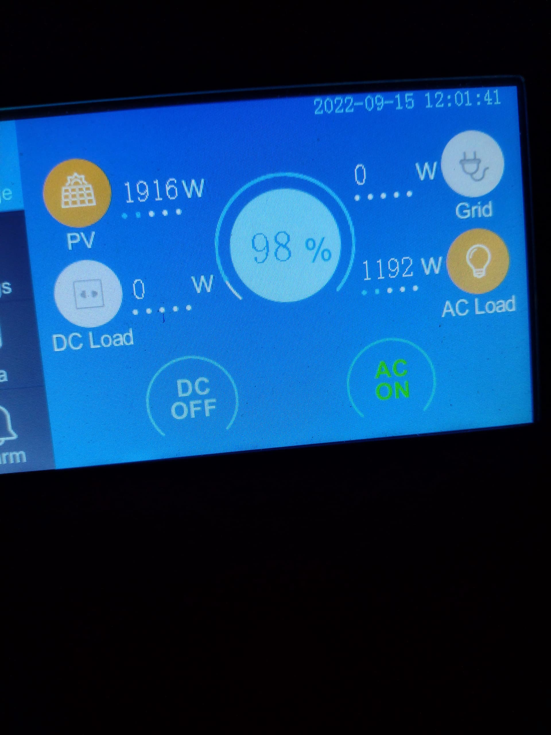
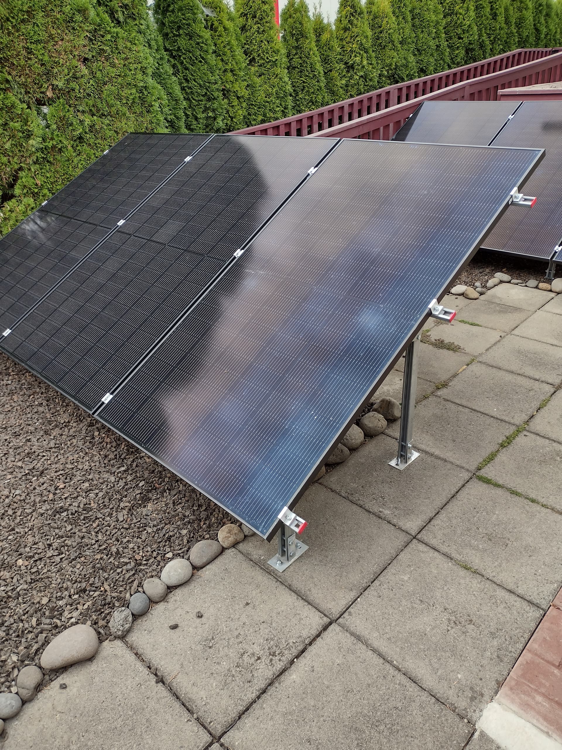
I talked with a Bluetti after sales engineer about solar panels and at the time I was looking at the Qcell Q-Peak BLK ML-G10+ 400W panel. These have no microinverters. He agreed that it met all of the specifications and should have no problem working with the EP500 Pro. They are 400W, VOC-45.3, IMPP -10.77A, SC-11.4A and I have 3 of these in series for 1200W. I have two sets of these for 2400 W total. These work very well and on one set I have gotten up to 1218W. I usually get at peak time over 2000W maximum on a clear day and varies between 1500W to 2200W depending on if it is totally clear. On a rainy day at peak time I will get around 300 to 500 W.
The panels are mounted on unistrut framing that has 4 sets of legs with two bolts each. I dug 10" x 18" holes and used 3" wide x 10" round cement forms at the top for a round flat surface of cement. Then on the 2" pavers I put 6" cement below the area where the legs were going to set and bolted into that area going a few inches into the cement. I used shielded cement bolts for the other 6 legs. This is rock solid but does sit a little lower than I would like but it goes above the local requirements for wind and all other criteria. This is in a mobile home park and things had to be down low according to park and local regulations. Thankfully we hardly ever get snow. If we do I will be shoveling.
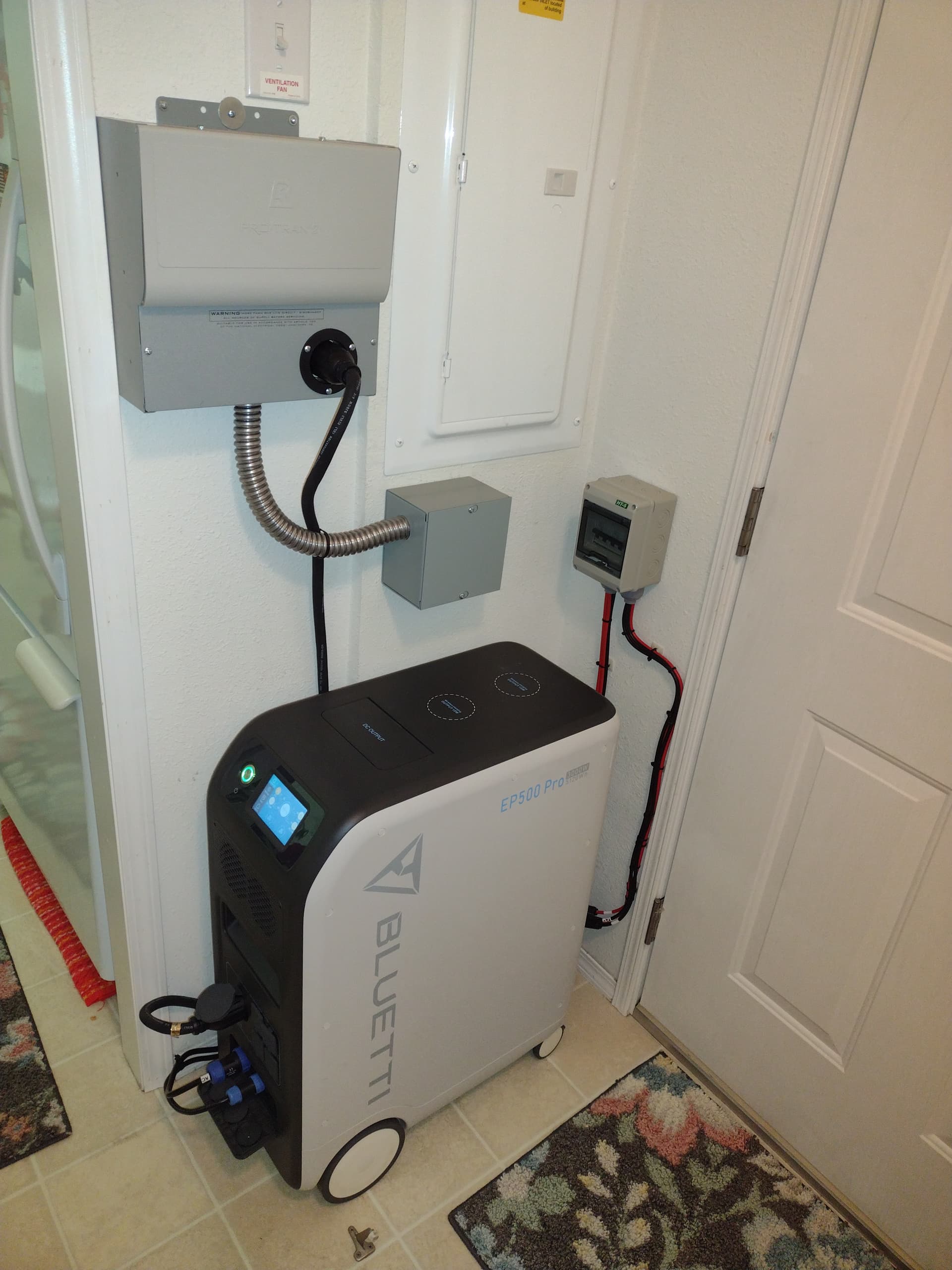
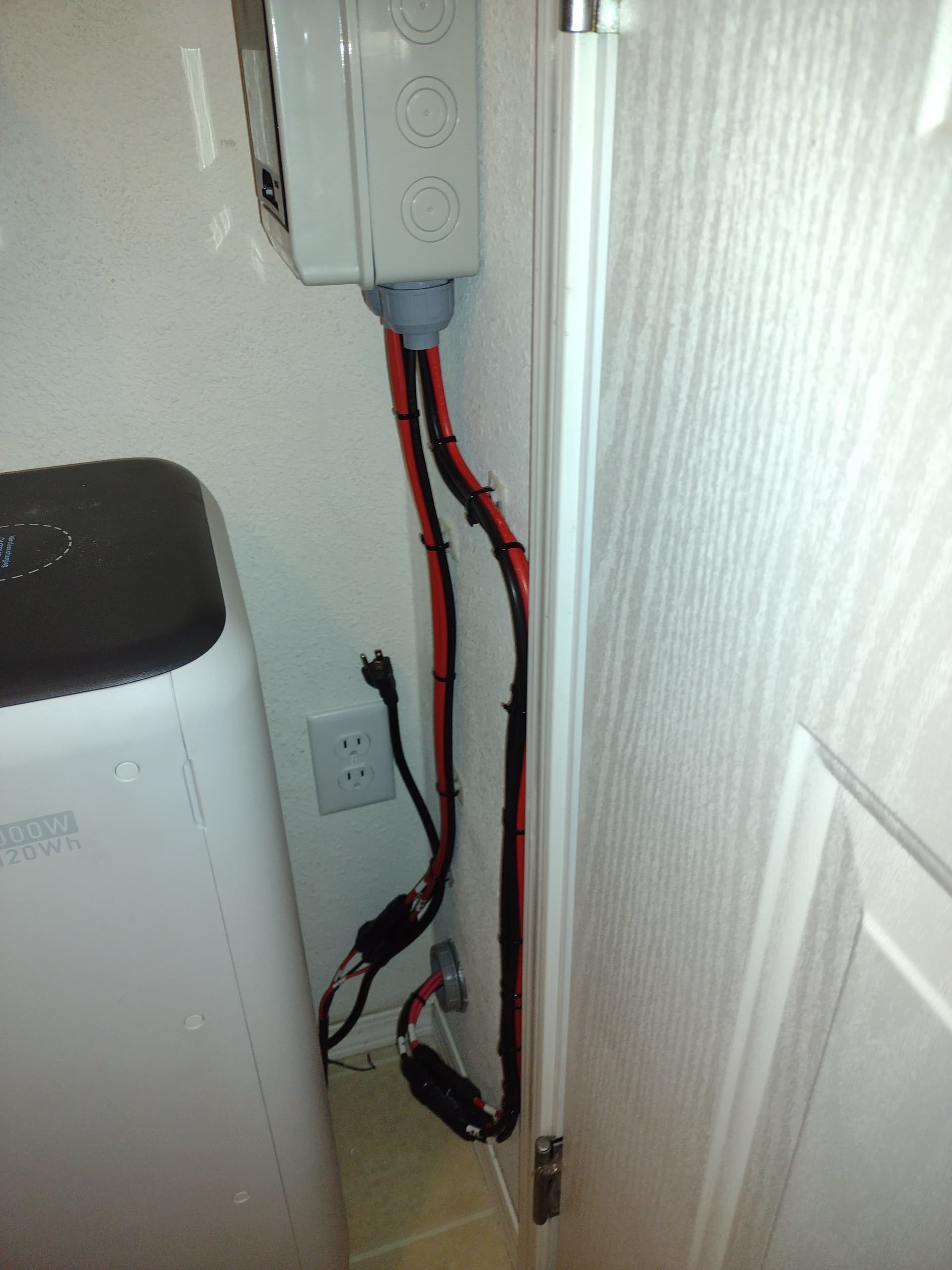
In the house behind the Bluetti I have 2-250V 16A DC breakers that I talked to this same Bluetti engineer about. I wanted to match up what the EP500 Pro was using. What I found was that with the AC and PV cable connected to the EP500 Pro I could not power down the unit, but would have to unplug these cables to reboot. At night this would not be a problem but during the day I wanted breakers to kill the DC power and unplug the PV cable. This would also give me access to breakers if there was a solar panel problem. I will turn these breakers off during thunder storms that thankfully we do not get very often. Even though everything is bonded and grounded properly on the solar panels and frame.
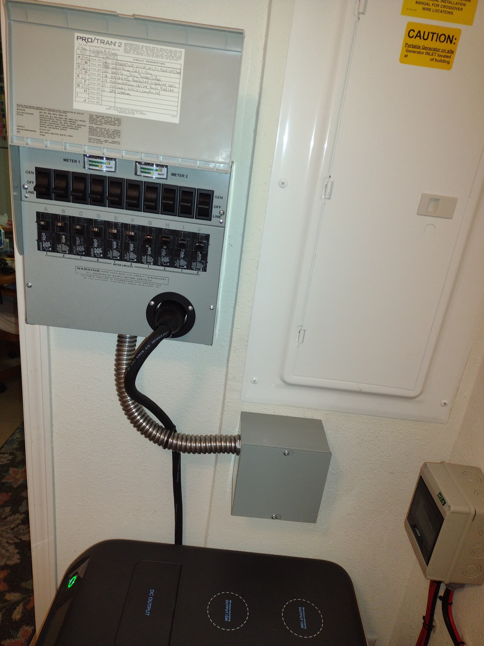
When it came to a Transfer Switch I worked with the same after sales engineer above along with people at Reliance. For my situation with no GFCI or AFCI breakers but just GFCI plugs the Reliance 310A Transfer Switch would work. I needed 7 circuits so this gave me 3 extra circuits if ever needed. They did not have an 8 circuit Transfer Switch available at the time. It was either 6 or 10. This Transfer Switch has worked good with no problems. In my case the Switch is next to the AC panel and above the EP500 Pro.
On the Transfer Switch I had to tie the X & Y legs together from the switch to the X leg on the Female L14-30 plug on the Transfer panel. I was doing this since it was just 1 EP500 Pro with 120V output. I used a 10 gauge wire that was wire nutted to the two legs and then screwed it into the X leg of the plug. I wanted this setup to where there would be no back feed from the Y leg. I put this to Reliance and they said that would be no problem with the way this was setup. And the Bluetti engineer agreed that this should work. After about a month of testing I have had no problems at all. I have had no Alarms or Error Codes on the EP500 Pro.
I bought a heavy duty 4 prong generator cable rated for 30A for this unit. This has done its job. I would like to see Bluetti make it possible to use the twist lock on the EP500 Pro housing. I am assuming that the EP500 Pro has a standard female L14-30 plug on the inside. I have the plug inserted all the way in with the cable situated to support the plug. With this setup I have no issues with the plug coming loose.
I have a AC vent that blows on the EP500 Pro and that helps to keep it cool. I have run this up to almost 3K watts for some time with no heating issues. I did not think the fans were loud at this wattage load. This unit stays very cool and in normal running mode I barely hear the fans when they are on.
In talking with the Bluetti Product Manager he told me that when plugging into the front AC plugs it is setup as a Floating Neutral generator. Then when you are using the L14-30 plug in a Transfer Switch it is just like a bonded Neutral generator. He also mentioned that he was working with Reliance and in about September or so Reliance was to have a Transfer Switch that would be designed for a single EP500 Pro. He did not explain all of the differences with this new Transfer Switch but I am assuming that the two legs from the switch would be already tied into the L14-30 on the front of the Transfer Switch for one thing. The reason I say this is because our discussion was mainly around the Transfer Switch, Neutral, and the problem of a single AC leg 120V coming into a 2 AC leg 240V Transfer Switch.
Hi @Jerry822 Thank you very much for the useful sharing of the installation and use of the EP500PRO. This will go a long way to helping some of our customers who are having trouble with the installation.
Thanks again for your willingness to write out this article!
I was just trying to help anyone that might have questions on panels and just what the EP500 Pro can do with larger wattage panels and what Transfer Switch works well.
I could not edit the post so here are a couple of notes. On the Reliance 310A to be more accurate it is the Reliance Pro/Tran 2 310A Transfer Switch. I made a mistake on the plug that is on the Transfer panel it should be Male and not Female plug. It is called an Inlet plug where the X & Y from the switch are tied to the X leg on the Inlet plug.
Thanks for the info. I have a very similar set up with my EPP 500 Pro and also used a Reliance Transfer switch. I ran into the same problem you did and the Reliance tech support was great. My problem was my switch was design to have one 240V breaker and 4 120V breakers. The fourth wire in the cord is for that purpose. A simple jump wire going from that to the 120v connections solved the problem. The switch should be marked 120v only to warn a future owner not to tie 2 breakers together
When I was young for a while I used to do electrical work, so I was trying to look at this in a variety of ways. I was even looking at using an Interlock on the main breaker, but you would have to make sure any 220V breakers on the chosen bus were turned off when using the generator and all 120V critical breakers would be on the same chosen bus. And your 30A breaker for the generator would have to be on that same 120V breaker bus at the top left of the breakers in my case for the Interlock to work. I decided on the Transfer Switch so we could use the generator at any time without affecting the 220V devices and we could save money on AC since we are using PV to charge. Also I wanted to make it easy on my wife in case I was not around when the AC failed. When I went to Reliance it was pretty straight forward and yes they were a big help. Between Bluetti and Reliance I was trying to cover all of the bases and it turned out good with the information that I was able to gather and they were both very helpful.
Thank you for sharing this. I am still a little confused by the L14-30 coming out of the EP500Pro. Are the X and Y both hot but in-phase. Or does one hot pin not have power? I have the same transfer switch you have and I want to make it work with just one EP500Pro. But I also have a 240V generator that I want to use for extended outages. So I didn’t want to tie the hots together. I can’t find any documentation for the pinout of the L14-30. Any insight would be appreciated. Thank you.
Brett,
On my unit it is only putting out 120V on 1 hot leg. The reason I wired both switch legs to the hot leg coming in was so there was no back feed on the other leg. I am assuming that both legs in the EP500 Pro are wired as would normally be setup on a Standard NEMA L14-30 plug as shown below in the link. When I first talked to Reliance support, he wanted me to just strap the two legs at the L14-30 plug. The reason for this was that you would have one switch wire going to each leg. You would end up with the use of all 10 circuits being fed off of one leg. One switch wire will power Breakers A, C, E, G, I and the other switch wire powers Breakers B, D, and so forth. What you could do is wire it normally at the L14-30 with a switch wire to each leg, at the switches you would only have use of every other breaker because you only have one hot leg and one hot switch wire for the 120V EP500 Pro setup. This would allow you to have the use of 10 breakers when running 240V and you would not care about the EP500 Pro because it would not be plugged into the L14-30 plug. The problem of course is just how many breakers do you need when running 120V off of the EP500 Pro this setup would only give you five 120V breakers. The other problem is if you have 240V breakers in this panel then you will be using let us say A & B so your load is shared evenly between the hot legs. I do not remember on this switch panel if you can use all 10 circuits as 240V. Some panels are limited to only certain breaker positions that can be used for 240V. With each 240V circuit you put into the switch panel you then loose one 120V slot for a 120V breaker. This would take some coordination between the Switch panel and the AC panel, and you are going to be very limited to both 240V and 120V breakers with this size Transfer Switch Panel. If you were to do this, I would run it by Bluetti and Reliance support just to make sure they see no problems.
You would need an electrician for doing this next procedure, but I believe it would work. You could use an Interlock Switch for the AC panel. The 30A two pole breaker would be tied into a different L14-30 plug for your 240V generator. In my case I have a Siemans panel with 4 breakers at the top for the main. The 2 pole 30A breaker goes in the top left slots for the 240V breaker that will feed the panel. You need to have the open slot positions to do this procedure also and maybe need to move some breakers to open the slots that you need. On the back of the panel cover the Interlock screws in and has to be lined up with both the Main and 30A generator breakers. Because when you shut off the Main breaker and engage the Interlock it prevents the Main breaker from being turned On, so linemen do not get back feed from AC panel. When the Interlock is switched to lock the Main the Generator breaker then can be turned on to feed the whole AC panel. The 30A breaker would be tied into a L14-30 plug that your 240V generator would plug into. At the Transfer Switch the switches would need to be set to Line. I would also unplug the L14-30 cable from the EP500 Pro generator for safety and totally isolate it. You would need to make sure your generator for this setup has the proper Neutral configuration. I believe that this would work but it would have to be verified by an Electrician to make sure that it meets all the Electrical codes, and they understand what you are trying to do and why. I have not looked anywhere to see if any others have done this or not. Because usually you are either going with a Transfer Switch or just using an Interlock and not mixing the two. This would take some research. I would go with the Interlock if this would work and you have the room for the L14-30 plug, because they are cheap. It costs about $68 a while back when I bought one for my panel, but I am not using it. You would also then have the whole Transfer panel dedicated to the EP500 Pro and use of all breakers for 120V.
Hopefully this helps and let me know what you come up with on your situation.
The EP500 Pro L14-30 wiring as below but I am assuming the X & Y are wired the same because it should be standard NEMA wiring for the US. The Neutral should always be across from the L shaped ground. Wiring of L14-30 Connector 125/250V