I agree with your assessment: for larger batteries, I will absolutely avoid Bluetti as long as they refuse to support local or DIY repair of their products. This is unfortunate - I was planning to purchase a large one in the next 12 months or so, likely a Bluetti as I had been quite happy with their products until this experience.
Instead, I plan to build with separate components as you described.
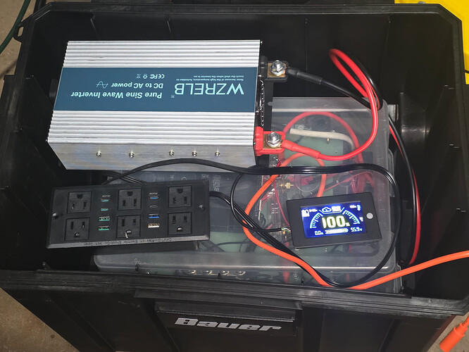
As for my AC200P, I don’t know that I’ll take it much farther than the picture I shared above. The 48V aftermarket inverter is working fine. I don’t have the fancy screen or other gadgets, but I also don’t really care about them. My daughter and I have enjoyed this project, so I might install an aftermarket BMS at some point - it looks like there are some solder-points that are fairly accessible for the individual BMS leads.
I really just have too many other projects on my plate to tackle an in-depth inverter board repair, although I admire your enthusiasm! The glue on this board is a serious pain. I checked for obvious things, like bulging capacitors or scorch marks - no clues.
This is the inverter I installed: Amazon.com: WZRELB 2000W Pure Sine Wave Inverter 48V DC to 110V 120V AC Power Converter with LED Display, Off-Grid Portable Power Inverter with 4 AC Outlets for Home, RV, Truck, Camping
That inverter is a pretty good value, and I see further up that the charging system still works independently of the inverter, which is pretty cool. Have you checked whether the MPPT works?
My feeling regarding the 100v2 is that it was an expenditure comparable to a mid-range mobile phone, so if it lasts 5 years that isn’t too bad. But a full sized system is more like a car and I would expect to be able to keep maintaining it as long as I want. AC200P and 200v2 are maybe sort of in between. The cutover might be at a box weighing 70 lb or more, since that has to be shipped by freight, while UPS and Fedex will take packages up to 70 lb.
Bluetti’s rationalization for not having repair documentation or parts availability is pretty weak, considering that people fix their own cars all the time, and TV repair was once a thriving local industry. TV’s back then had CRT’s with as much as 20,000 volts from the flyback coil. Similar with power tools, home wiring, etc. I’m much more scared of a gasoline powered chain saw than I am of an inverter board…
Now I’m wondering if I have to pay the shipping costs if someday I need a 100v2 warranty repair. Hmm.
Can I ask what they wanted to charge you to repair your 200P?
I see someone on DIYSF has a 200P with some solar panels for sale. I’m not looking for anything like that but the offer seemed generally reasonable, depending on the warranty situation. The unavailability of repair info certainly damages the aftermarket for out of warranty units.
I am operating under the assumption that the inverter board handled MPPT. Both of the charging ports were routed through the inverter board. I was able to bypass it for the 56V DC input from the charger and connect that right to the BMS, but I don’t see any circuitry on the BMS that would suggest that it is capable of MPPT. That function of the inverter board won’t work either, because it routes that power through the same terminals that are currently shorted.
100% agree. It seems more like a marketing/sales-oriented decision than a customer-satisfaction decision.
They wouldn’t tell me until I shipped it to them. That’s a pretty hefty expense to pay just to find how much more it will cost to repair it - which was a big part of why I declined.
Time on even their extended warranty is ticking away for this model, so I wouldn’t spend much on it unless I was ready and willing to install aftermarket circuitry. If the battery fails, it’s probably not worth even a DIY repair because you’d have to replace the battery, BMS and inverter. At that point you might as well just buy a new unit, or build your own.
Inverter and MPPT are usually separate devices when you buy components, but Bluetti may have combined them on the same board as an optimization. In that case maybe you have no MPPT. On the other hand you have a 2000W 48V inverter, an AC charger, and 2 KWH of batteries. The batteries are good for a lot of cycles and don’t seem likely to fail, so if the charger holds up and if you don’t care about solar, then you have a decent power bank. You can always DIY something later, using whatever works from the existing parts.
Gonna add, if you have already managed to disconnect the battery pack, I wonderif Bluetti would let you send either just the inverter board, or else the whole unit but minus the batteries, which would save a lot of weight.
Gonna add, if you have already managed to disconnect the battery pack, I wonderif Bluetti would let you send either just the inverter board, or else the whole unit but minus the batteries, which would save a lot of weight.
After some back-and-forth, Bluetti politely reiterated that they would not be selling replacement parts for this battery station, or any other battery stations - nor would they provide an estimate of what it would cost if I sent it in. They did give me 2000 “Bluetti Bucks” - a nice gesture.
So down the rabbit hole we continue!
As I continued this fun and educational project with my daughter, we next replaced the BMS.
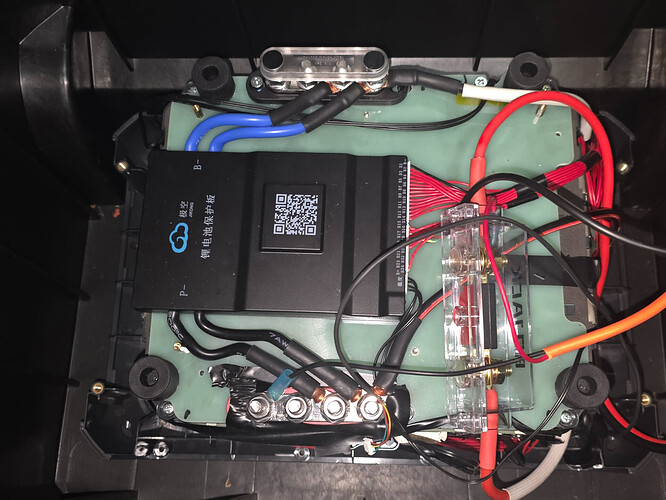
The BMS can be removed with a few small screws on top of the battery pack. Once removed, you can remove some much longer screws that attach the pack to the bottom of the case.
Next, if you tear off the cardboard covering the circuit board on the front of the battery pack itself, you’ll see that the terminals are nicely labeled B0-B16!
(Please try to ignore my terrible soldering job, I’m slowly getting better)
I needed these connection points to connect the voltage sensing leads for the BMS. Since it is a 16S4P system, it needs to be able to monitor the voltage of 16 sets of 4 parallel cells. Each set of parallel cells should measure around 3.3V.
If the connection points weren’t labeled, they would be easy enough to identify. B0 should have continuity with ground. Find the connection point with 3.3V drop to ground, and that’s B1. 6.6V drop to ground, that’s B2. And so on.
I selected the JKBMS 8S-20S 24V-60V 150A BMS to replace the OEM Bluetti BMS. I selected it because it has an android app to monitor cells, it was a good price, and has surplus capacity in case I want to build a larger battery pack with it someday.
I soldered the 16 leads for each set of cells (B1-B16), one to the common (B0), and one to the positive output cable on the side of the pack. One of the B- leads on the BMS goes to the ground on the side of the battery pack.
I hit the BMS power button, and we’re off to the races! Android app is showing the cells are fairly healthy. I’m hoping this BMS will do a good job of balancing them once I get a good charger for it.
Through the app I was able to enable power output - and measured 53V on the BMS output!
I’ll try to keep updating as we make progress. This is a spare-time sort of project. Hope someone finds it helpful!
I procrastinated on this project and then an unplanned boondocking (off-grid) trip came up. So we decided to finish it up quick-and-dirty to use on the trip, using mostly things I had laying around. I know it’s not a clean install, don’t drag me too hard please.
First of all, the 16 sets of cells were rather unbalanced once I put a load on them. I think the Bluetti BMS had passive balancing, but it must not have done a very good job. I very carefully used my adjustable DC power supply to charge 6 of the 16 sets to equalize it a bit, then I did a very gradual charge on the whole pack and the BMS got it balanced in a day or two. By my rough measurements, this increased the usable capacity from 28AH to more like 34AH. It could go higher, but I have the BMS configured pretty conservatively to maximize the lifespan of the pack.
There are some existing nuts/bolts holding the battery pack together - I used some of those to bolt down the two 150A distribution blocks for P- and B- coming off the BMS. I also had a bojack 80A ANL fuse around, so I used that on the positive cable coming off of the battery pack.
The negative lead from the battery pack goes to B- on the BMS and the BMS closes the circuit to P- when discharge is enabled. I ordered this so I could use the original Bluetti charger. The positive end connects to the fused side of the Bojack fuse. The negative end connects to the P- distribution block. Then I connected the inverter to the same places as the charger - the charger and inverter are essentially parallel in this configuration.
The BMS has a connector for an LCD display/power-button. I ordered this display from AliExpress a few weeks ago and it finally came in.
I dropped the battery pack in a cheap Harbor Freight wheeled toolbox. Put a few vent holes in a plastic bin to cover the battery pack, dropped in the remaining electronics - and done.
(There are plastic caps to cover the inverter terminals, they’re just not shown in this photo)
The battery performed very well on our trip. It can run a box fan for a few nights as well as charge your phones.
Overall, it cost me around $200 to make a working battery station out of this ($300 including the new BMS, but that wasn’t strictly necessary). It’s certainly not as sleek as the original Bluetti case, but I’m pleased with it.


